Timers
What are the uses of a timer peripheral?
time base generation
measuring/counting input signal frequency (measuring time periods of waveforms)
producing different wave forms
measuring pulses width
generating pulse width modulation (pwm)
triggering external devices (use timer to trigger Adc/dac conversion)
What does a Timer do?
at the basic level it counts from 0 to some pre programmed value (up counting) or from some pre programmed value to 0 (down counting)
so the job of the timer peripheral is just to count
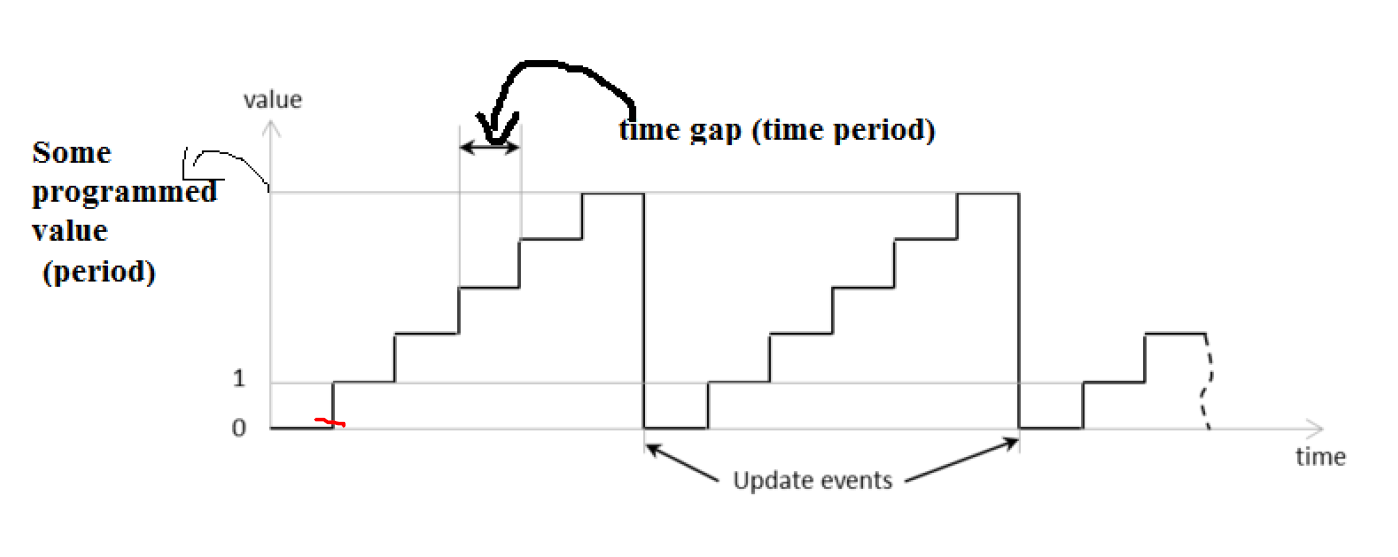
Lets say the timer is configured by programming a value of 5 into its configuration register. Once this configuration is set, the timer can be enabled for counting. It starts from 0 and counts sequentially through the values: 0, 1, 2, 3, 4, 5. Upon reaching the programmed value of 5, the timer indicates that its counting period is complete.
After completing its count, the timer resets and rolls back to its original position, which is 0. This reset prepares the timer to start counting again from the beginning. However, before it initiates the next counting cycle, the timer generates an update event. This event serves as an important signal within the timer's operation.
The update event has the capability to trigger an interrupt. This means that when the event occurs, it can interrupt the processor, allowing for immediate attention to be directed to the event. This functionality is crucial for applications requiring timely responses or actions based on the timer's status.
The gaps between counts in a timer represent the time intervals between increments.
Large Gaps indicate lower frequency, meaning each count takes more time. This is useful for applications that don’t need precise timing and typically results in lower energy consumption. Visually it can look like
1 2 3 4 5
Small Gaps suggest higher frequency, where counts occur more rapidly. This is beneficial for applications requiring precise timing but may lead to higher energy use due to more frequent interrupts.
1 2 3 4 5
So the time gap or time period refers to the duration between two successive events or counts in a timer. It indicates how long it takes for the timer to increment from one value to the next. A shorter time period means faster counting, while a longer time period indicates slower counting. The clock frequency of the timer peripheral determines this.
Higher frequency = smaller gap
Low frequency = big gap
Types of STM32 Timers
Basic Timers: Simple timers used for basic counting functions and majorly used for time base generation. It is suitable for measuring time intervals or creating delays.
- these timers do not have input/ out channels associated with them
General Purpose Timers: More flexible than basic timers, these can handle event scheduling, periodic interrupts, and PWM generation, making them versatile for various applications.
Advanced Timers: Feature-rich timers with high-resolution counting and complex functions like input capture and output compare, designed for demanding tasks such as motor control and precise measurements. (only some STM32 MCUS)
Best to refer to the Application note STM32 cross-series timer overview datasheet for your board
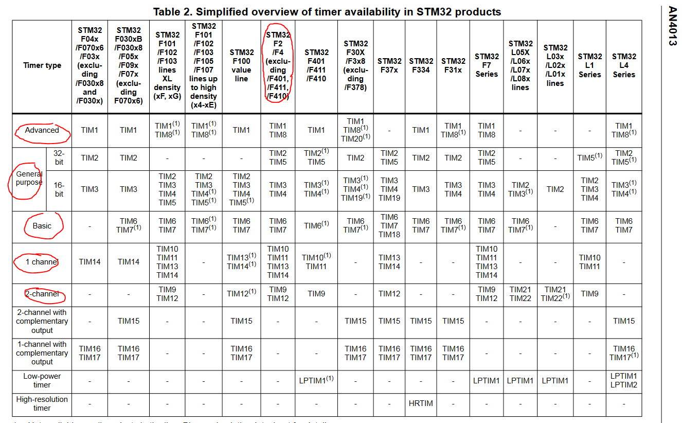
I have the STM32F446 so those are the type of timers i have. I have access to 1 advanced timer, general purpose timers either 32 bit or 16bit, basic, general purpose with 1 channel or 2 channel timers. I have total of 14 timer peripherals.
How does it work
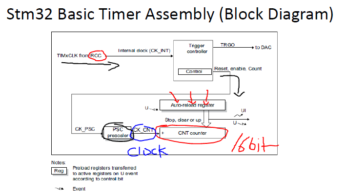
This is a basic timer block diagram taken from the data sheet to understand how it works.
The main clock source to drive this register starts in the TIMER CLOCK from the clock control register. It then passes through a trigger controller block, which serves as an API to enable various functions such as reset, enable, and count. After this, the signal goes into a the prescaler (it is used to divide the main clock frequency to adjust the timer's counting speed for further modification before reaching the counter register.)
After the signal passes through the prescaler, the clock frequency (CK_CNT) is determined and drives the 16-bit counter register, which establishes the counting speed. The Auto Reload Register (ARR) defines the maximum count value, determining how long it takes for the counter to reach its limit and reset. Together, the ARR and prescaler dictate the timing intervals and frequency of the timer’s output or generated interrupts.
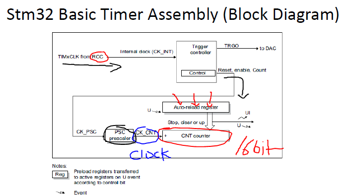
Time Base Unit
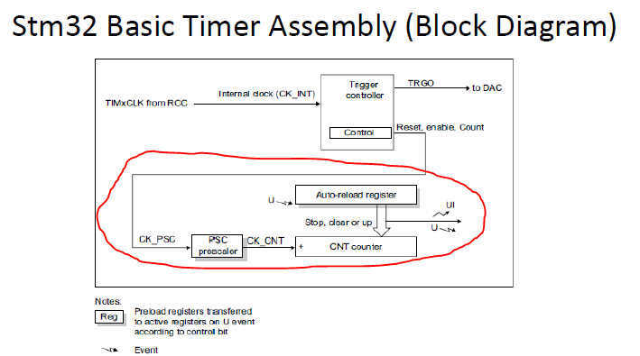
includes: 16 bit up counter, counter register (TIMx_CNT), pre scaler register(TIMx_PSC), auto reload register(TIMx_ARR). This will come in handy when implementing the driver.
%[INVALID_URL]